LED upgrade
Last time we used a tiny light that is built into the Arduino to test everything was working and to start learning about code. Now we’re going to upgrade to bigger, better, brighter lights, as well as explore adding more than one light at a time. The lights we’re using are called LED lights, or Light Emitting Diodes. Using the one on the Arduino is easiest because it’s already wired up, but we’re going to have to wire up all the new ones ourselves.
Testing an LED
We need to be able to check if an LED is working, so that if our finished product isn’t working, we know it’s not because the LED is broken, narrowing down the problem. The easiest way is to plug the two legs on an LED into pins 13 and GND as shown in the picture. LEDs only work in one direction of electricity, so it’s important to make sure that the long leg goes into the 13 hole while the shorter leg goes into GND.

Be careful! The long bendy legs are easy to accidentally bend, and sometimes the holes we’re pushing them into are a bit tight. A wiggle is better than pushing harder!
Load up your blinky code from last time and make sure the new light is lighting up to match the on-board LED.
Doing it properly
Unfortunately, pin #13 is the only one we can plug an LED into like this. This is because pin 13 is set up with the LED already, and so it includes a resistor to protect the LED from excess current. Plugging in an LED to another pin without a resistor would break the LED (or maybe even the Arduino). This is because the Arduino happily pushes 500mA of current down each pin, but an LED only wants about 30mA. If we add a resistor, we can restrict the current down to a level that everything is happy with.
We will need
- a coloured LED of your choice
- a 200Ω resistor
- 2 wires (best if 1 long and 1 short wire)
The colour of the wires don’t matter. It’s nice to use colour coding, but not necessary while things are small like this.
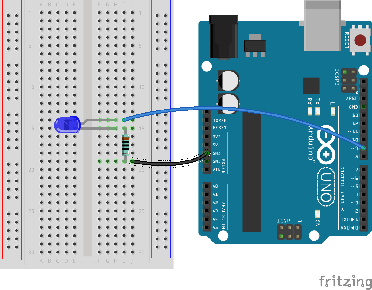
Wire up your new pieces as shown in the picture. Note the “bent” leg on the LED. This indicates it’s the long leg, and goes in the numbered pin, while the straight leg is the short one and will be connected to GND. You’ll find it easier to wire it up if you do it in the following order:
- Bend the resistor into a ⊔ shape and insert the legs into two holes
- Line up the short leg of the LED with one of the legs of the resistor, so it goes into the same ROW as the resistor leg
- Line up the long leg one row higher
- Push the LED in
- Add the wire that connects the other resistor leg to GND
- Add the wire that connects the LED long leg to #9
If the picture is too small, right click it and choose “Open image in new tab” to make it bigger.
If you’re paying attention, you’ll notice we aren’t plugged into pin #13 any more. We’ll need to change our code to use the new pin number. Load up the blink code, change all the 13s into 9s, and upload the code. Make sure the light works!
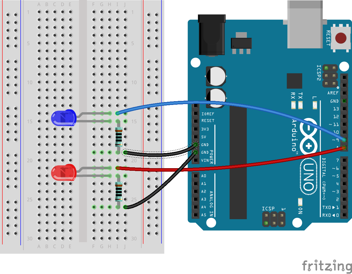
More lights!
Now, after doing all that work to get 1 light working, getting two lights is just some copy-paste work. First, lets wire up the second light. You’ll need another LED, another resistor, and 2 more wires.
Once you’re wired up, we’re going to go through our code in 3 sections to make both lights work. Look at each section, find what’s different, and use copy-paste where you can to save typing so much.
| Old Code | New Code | ||||
|---|---|---|---|---|---|
|
|
||||
|
|
||||
|
|
The first two parts are pretty easy. We just changed the name from LED to LED1 and LED2 because the two lights need different names in the code. We have to copy the pinMode line as well, otherwise the Arduino won’t give enough power to the new LED.
Understanding the code
The third part is a bit more complicated. Let’s have a closer look. Each line of code matches to one line of explanation on the side.
|
We always need a void loop |
||
|
Turn LED1 on |
||
|
Turn LED1 off |
||
|
Always the last thing in the file |
Test out the new code, and make sure it’s working how you expect.
Wrapping up
Try the following challenges to prove you understand what’s going on!
- Make the lights blink alternately (one on, one off)
- Make the lights blink at the same time (both on, both off)
- Make a red light that stays on for a long time (use
delay(5000for the delay) then a green light that flashes a few times (Like a pedestrian crossing)- Make a police car siren lights (3 fast red flashes, 3 fast blue flashes)
- Add a third light and make traffic lights (Red for a long time, Green for a little time, Orange for a medium time)