Pushing buttons
While the LED and buzzer are great to play with, and you can do a lot of things with them such as interactive signs, fancy christmas trees, and annoyotrons, it would be nice if we could actually make the Arduino do stuff when we tell it to. Lights and buzzers are outputs which mean they get information OUT of the Arduino and into our eyes and ears. It’s time we started looking at getting information IN to the Arduino with an input. And the simplest input is a button.
Later, we’ll use light sensors, volume knobs, and even explore things like moisture detectors and thermometers. But buttons are the first step, just like 1 LED was our first step.
Keep in mind, a button isn’t just a “thing you push with finger.” Roomba vacuums use what are basically giant buttons to tell if they’ve hit a wall. The interior light of your car uses a reverse button (if the button is pushed, the door is closed, keep light off). Buttons open up a LOT of options.
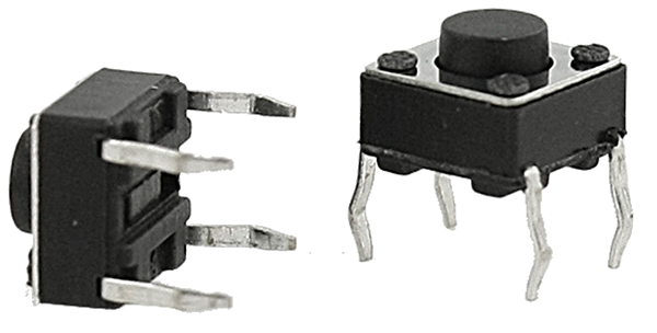
The buttons we’re using are called “momentary switches” and they come in all shapes and sizes. The one’s we are using look like this (but about the size of your pinky nail):

Weird things first
There is one trap people fall into with buttons on Arduinos. To make the wiring easier, the coding is backwards. LEDs turn ON when HIGH. Buttons when we use the PULLUP shortcut are PRESSED when LOW. We’ll add a line of code near the end to make this easier to read without getting mixed up.
Wiring
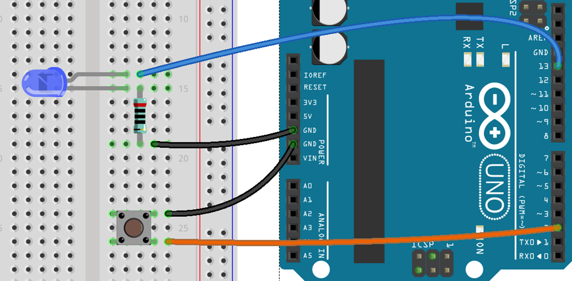
You probably still have an LED and a buzzer wired up. That’s fine, they can stay, just make sure the LED is wired into pin 13 as shown. If you don’t, you’ll need to rewire an LED back up first. Then add a button to pin 2 and GND. The legs on the button can be a bit tricky to keep in the holes. Just make sure they go ACROSS the breadboard, not UP+DOWN.

Code
Remember the way we have been writing code so far usually has 3 sections:
- Code at the top to define numbers and variables we want to use
- Setup to say how each pin will be used
- Loop to actually do stuff
This will be the same. Start a new Sketch (a new file in Arduino IDE)
Part 1 - Define the variables
We need two numbers. One for the LED and one for the button. These have to match up to the ones we wired up to. Maybe you should try using different numbers in different pins when you’re done?
1
2
const int buttonPin = 2;
const int LED = 13;
Part 2 - Setup
Now we tell the Arduino what these 2 pins do. Note that the button one is different to everything we’ve done so far. This is because everything else has been an output. Now we’re doing an input (and using pullup as a trick to make wiring easier).
1
2
3
4
void setup () {
  pinMode(buttonPin, INPUT_PULLUP);
  pinMode(LED, OUTPUT);
}
Part 3 - Loop
We’re going to start super simple, then make it better later. Make your loop code look like this:
1
2
3
void loop () {
  digitalWrite(LED, digitalRead(buttonPin));
}
Test it!
Click the tick in the upper left corner of the screen. This will check if the code is valid. If it says “Done compiling” in the bottom right, you’re ready to go. If it turns orange, something went wrong. Double check the 3 sections above look the same.
Once the tick passes, click the upload arrow next to it. When it says “Done uploading” try out your button.
If you get “Problem uploading to board” it means you forgot to set the Tools > Port setting. Or you’re not plugged in.
It’s alive!
Your button should control the light. It should be on all the time, and turn off when you press the button. That’s not a very “normal” use for a light. Let’s make it work backwards, by adding a single character to our code and not touching the wiring. Change the line inside loop so it looks like this:
1
  digitalWrite(LED, !digitalRead(buttonPin));
And then test it again by uploading your new code.
Too clever
We’re being clever and doing a lot of stuff at once here. It’s worth explaining each bit:
1
2
  digitalWrite  (  LED   ,       !         digitalRead  (  buttonPin  ));
  Set The Value ( of LED ,  to opposite    ofWhatever   ( theButtonIs ));
digitalWritesets a pin (before the comma) to a value (after the comma)LEDis the pin we are setting (pin13)!flips whatever is after it to it’s oppositedigitalReadsees if an input is on or off, remembering that PULLUP buttons are backwardsbuttonPinis where the button is
Don’t worry, it only gets more confusing! Practice helps a lot.